LumeLevel RS485 Sensor Bus v1 — M12 Installation Guide
This is the field-installation standard for the LumeLevel four-wire RS485 Sensor Bus used by supported Pebble Eco 2 and Pebble Plus installations. New Bus v1 installations use keyed M12 4-pin A-coded plug-and-play components from the Pebble to the final 120 Ω bus-end terminator.
The Bus v1 standard
The installer works with complete connectors and approved adapters rather than constructing the normal RS485 trunk conductor-by-conductor in the field.
Components the installer will handle
Pebble RS485 bus port
The Pebble presents the female M12 Bus v1 connection and forms the controller end of the RS485 trunk.
M12 trunk cable
Use approved M12 4-pin A-coded male-to-female trunk extension cables between the Pebble and T-distributors and between successive T-distributors.
M12 T-distributor
The T-distributor has a male trunk-in connection, female trunk-out connection and female sensor-branch connection. The trunk passes straight through the T.
M12 sensor drop
Use an approved male-to-female M12 drop from the T-distributor sensor port to the sensor or sensor adapter. Maximum drop length is 2 m.
Sensor adapter
Where the selected sensor does not itself present the LumeLevel M12 Bus v1 interface, use the approved sensor-specific adapter. The adapter presents a male Bus v1 connection to the drop cable.
120 Ω M12 bus-end terminator
The removable male M12 terminator plugs into the unused female trunk-out port of the final T-distributor. It terminates the physical far end of the bus.
Illustrated component reference
Illustrative component reference — component appearance may vary by approved supplier.
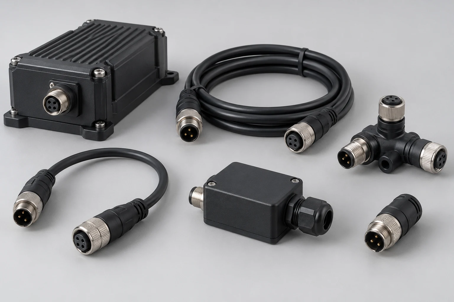
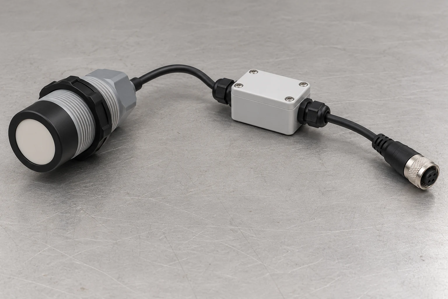
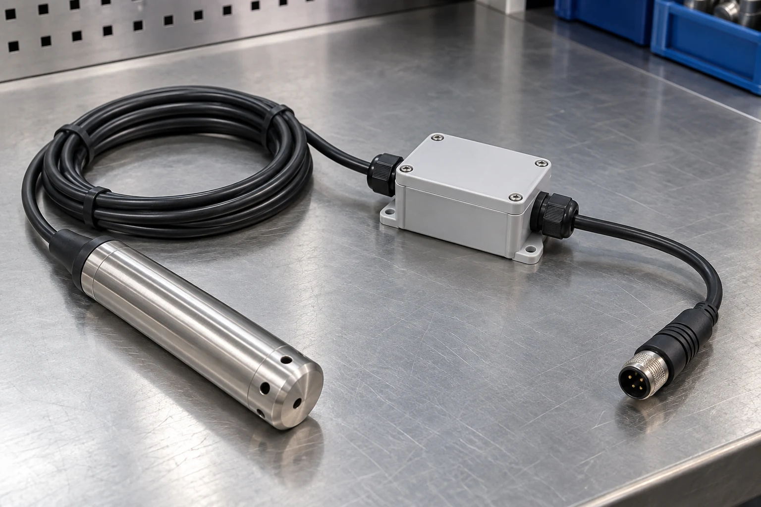
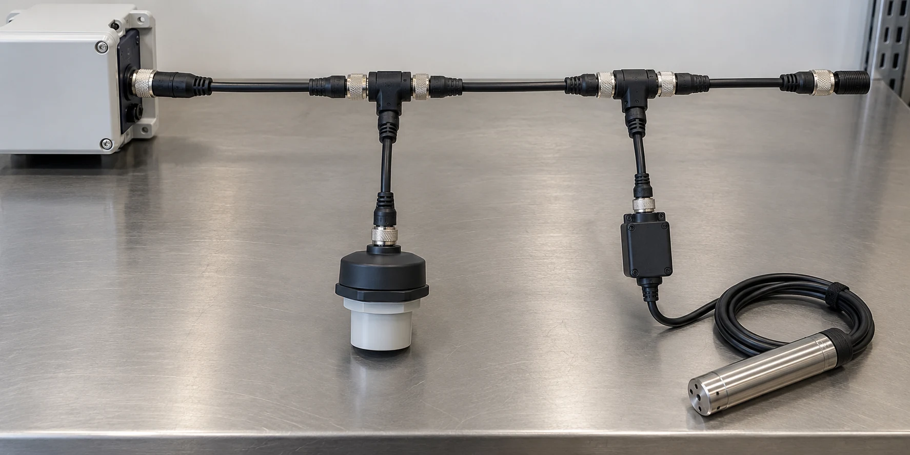
Illustrations are for component recognition and installation context. Connector pinout and topology diagrams remain authoritative.
Correct physical topology
Use one T-distributor for each standard sensor location. The trunk continues through every T; the sensor leaves the trunk on the short drop.
Pebble → trunk → T → trunk → T → final M12 terminator, with each sensor connected on a short drop from its T-distributor.
One point feeding several long passive branches, a T-distributor installed on another sensor drop, or multiple terminators placed at sensor locations.
M12 4-pin A-coded electrical assignment
This pin assignment is fixed across LumeLevel RS485 Sensor Bus v1 components. Connector keying and the standard conductor colors are used to keep every manufactured cable and adapter consistent.
| Pin | Standard color | Bus v1 signal | Function |
|---|---|---|---|
| 1 | Brown | +12 V | Protected field-power rail |
| 2 | White | LL-D− / RS485 B | RS485 negative / B data conductor |
| 3 | Blue | LL-0V / GND | Field-power return and common reference |
| 4 | Black | LL-D+ / RS485 A | RS485 positive / A data conductor |
Model and bus limits
| Item | Bus v1 limit |
|---|---|
| Pebble Eco 2 | Maximum 2 supported RS485 nodes |
| Pebble Plus | Maximum 6 supported RS485 nodes |
| Trunk length | 100 m maximum |
| Individual sensor drop | 2 m maximum |
| Controller-end termination | 120 Ω termination provided by the Pebble RS485 hardware |
| Far-end termination | One removable male M12 120 Ω terminator at the final trunk-out port |
Field installation sequence
- Confirm the design before mounting. Identify the Pebble model, sensor count, sensor types, T-distributor locations, drop locations, trunk route, power source and final terminator location.
- Confirm the components. Use the correct M12 4-pin A-coded trunk cables, T-distributors, sensor drops, approved sensor adapters and one far-end 120 Ω terminator.
- Route before final connection. Keep the cable supported and protected from sharp edges, crushing, repeated movement, standing water where the component is not rated for it, and avoid unnecessary parallel routing beside high-current pump or mains conductors.
- Connect with power isolated. Align the A-code key before engagement. Never force or cross-thread the connector. Seat the connector fully and secure the threaded coupling without allowing cable weight to load the connection.
- Build the linear trunk. Connect the trunk through each T-distributor in sequence. Connect the sensor on the dedicated short drop port. Do not install another T-distributor on a sensor drop.
- Install the far-end terminator. Fit the male M12 120 Ω terminator to the unused female trunk-out port of the final T-distributor.
- Power and configure systematically. Where device addressing is required, configure or verify addresses methodically so every active node on the bus has a unique address.
- Verify the complete bus. Confirm every required node responds, every configured sensor matches the real installation, readings are plausible, and communication remains stable with the complete intended bus connected.
- Secure and document. Complete final cable support and weather protection, then record the sensor/address/tank relationship and any installed sensor adapters for future service.
What not to build on Sensor Bus v1
Sensor adapters and non-M12 sensors
Some supported sensors or interface modules may use their own native pigtail, terminals or connector. That does not change the Sensor Bus v1 trunk.
Supported sensor examples
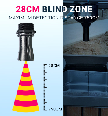
Pebble-A01 RS485 ultrasonic
Mount and aim the sensor for the required measurement geometry. Connect it to Bus v1 using its approved M12 interface or sensor adapter rather than modifying the trunk.
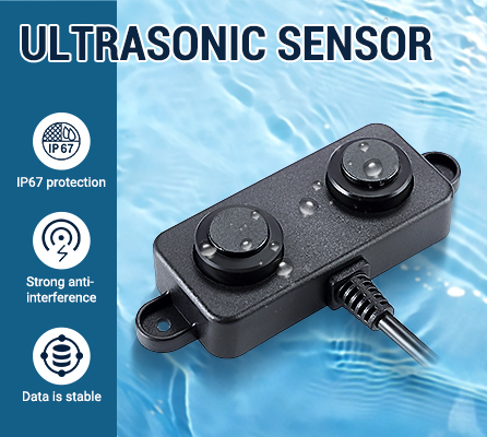
Pebble-A02 RS485 ultrasonic
Use where the selected tank geometry requires the supported shorter blind-zone ultrasonic option. Preserve the same M12 Bus v1 topology.
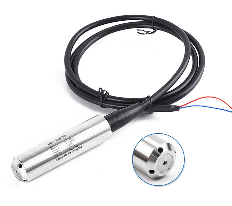
Pebble-300 submersible
Protect the sensor cable and any vent/reference arrangement required by the selected sensor. Use the approved Bus v1 sensor adapter where the sensor does not provide the standard M12 interface.
Bus v1 commissioning check
A bus that communicates once is not automatically a commissioned installation. Confirm the complete physical and configured system.
- Pebble model and permitted node count match the installed system.
- The trunk is linear and remains within the 100 m Bus v1 limit.
- Each sensor is connected from a T-distributor on a drop no longer than 2 m.
- No T-distributor has been added to a sensor drop.
- The final trunk-out port contains the removable M12 120 Ω terminator.
- Every required RS485 node has the correct unique address and supported communication settings.
- Every M12 connection is correctly keyed, fully seated, secure and appropriately protected for its installation environment.
- Each physical sensor, portal sensor type, tank relationship and live reading agree.
- The complete bus remains stable after final cable routing and securing.
Bus v1 troubleshooting order
Safety and stop-work boundary
- Isolate power before altering connectors, replacing damaged bus components, opening an approved sensor adapter for conductor-level work, or performing work that does not require energized operation.
- Do not probe energized conductors unless the person performing the work is competent, authorized and using an appropriate safe electrical work method.
- Stop and escalate when diagnosis or repair exceeds the installer’s qualification, site authorization, equipment or safe access.
- An intermittent bus, damaged M12 connection, missing termination, unresolved power problem, unreliable reading or unexplained communication fault is not a commissioned condition.
Component identification standard
LumeLevel installer material for Sensor Bus v1 should show the hardware an installer actually handles: the Pebble, M12 4-pin A-coded trunk cables, M12 T-distributors, short M12 sensor drops, approved sensor adapters and the removable M12 120 Ω far-end terminator.